 |
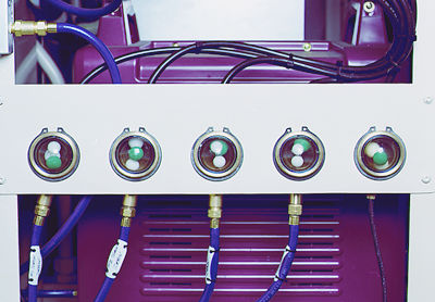
The above diagram shows a typical installation set-up for the MPC Visual Flow Indicator, to help ensure proper flow is reaching the working application. Of course, a VFI can be placed at any point on your line where you want to monitor flow. A VFI unit can be installed in virtually any orientation without compromising the unit's performace. |
 |
More Information about MPC Visual Flow Indicators:
 A Closer look at the VFI Components
Pressure Drop Chart
Request a Quote
Apply for Credit from MPC
Back to VFI General Information
![]()
![]()
![]()
![]()
![]()
![]()
![]()